[Electronics] Dissecting a Vibration Activated Sound Module
Examine the inner workings of a talking stuffed car with me.
What’s inside a noisy toy?
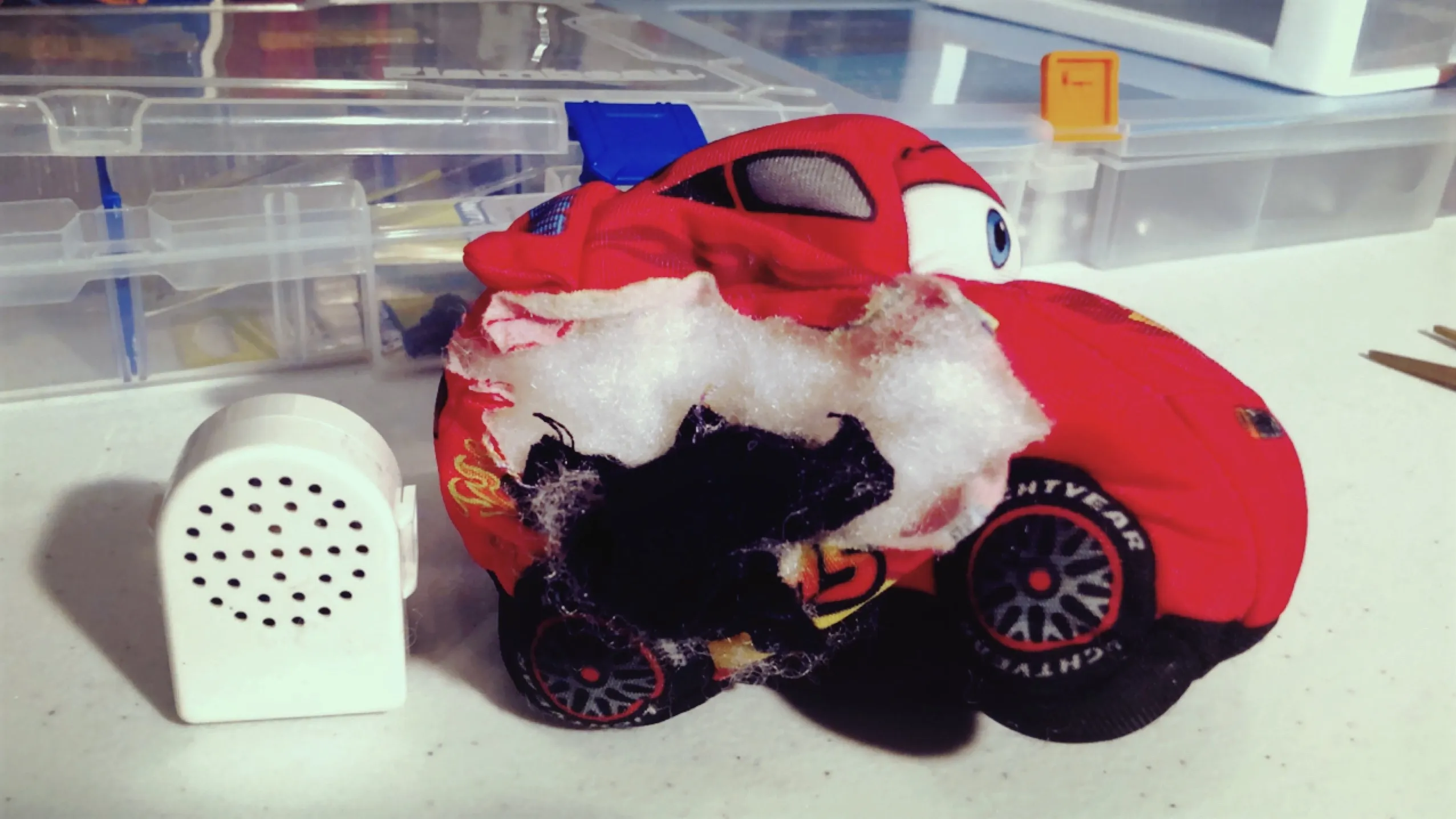
As I was sifting through a piles of stuff at my local thrift store outlet’s bins, I heard a faint vrooom-ing and yelling of Cars II movie quotes coming from the depths of a disorganised mass — a talking Lightning McQueen stuffed car! While digging him out I figured that my jostling was somehow triggering these sound clips to play. After I got home, I cut him open and plucked from his belly the topic of this post: an electronic, vibration activated sound module.
The module consists of a vibration sensor, mini speaker, printed circuit board with a chip, and batteries.
I was curious about how it worked, and since this was one of my earlier and more thorough hands-on learning efforts, I thought I would share my findings and practice writing about electronic components.
Overview
My main goals were to identify and understand as many parts of the module as I could, and by doing so, become more familiar with electronics. To that end, I will be pointing out and discussing the module and its individual components in detail.
The Module’s Case & Taking the Module Out
The module was enclosed in a small plastic case which was tucked inside a thin black cloth pouch. The pouch was stitched to the inner base of the toy car to prevent the module from slipping around and causing the toy to feel lumpy in the wrong places.
The plastic case has a speaker grill on the lid and is secured on three sides with cantilever snap fits. Cases designed with snap fits like these become quite firmly “locked” in place after being assembled and don’t appear to be meant for easy or frequent reopening.
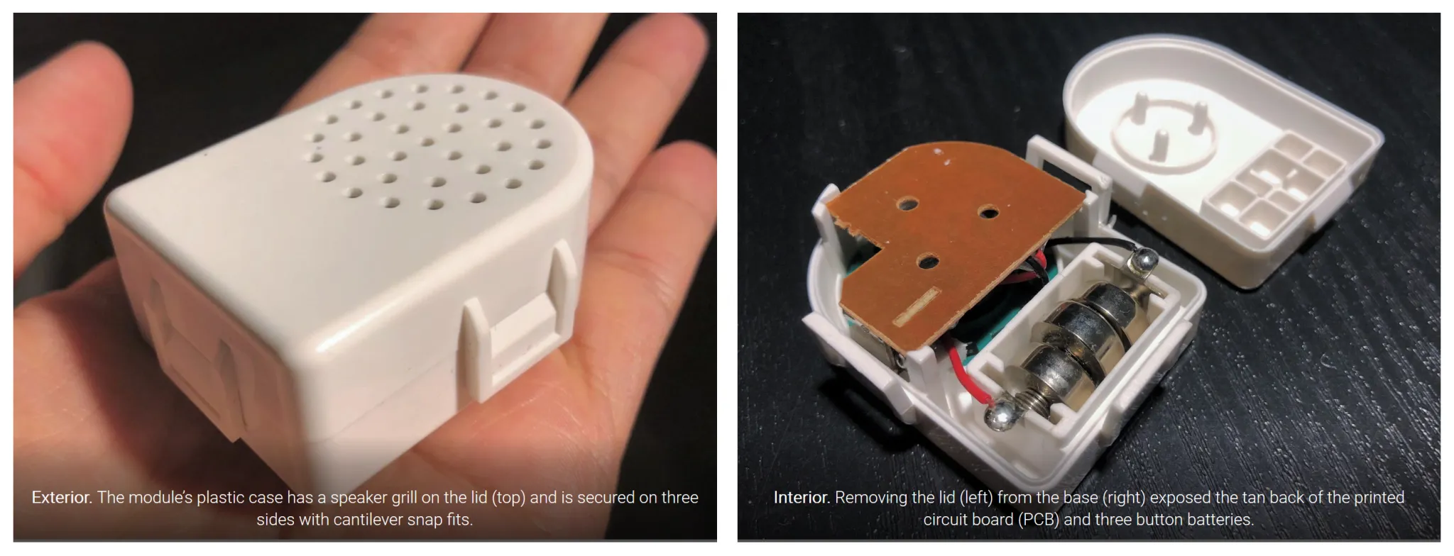
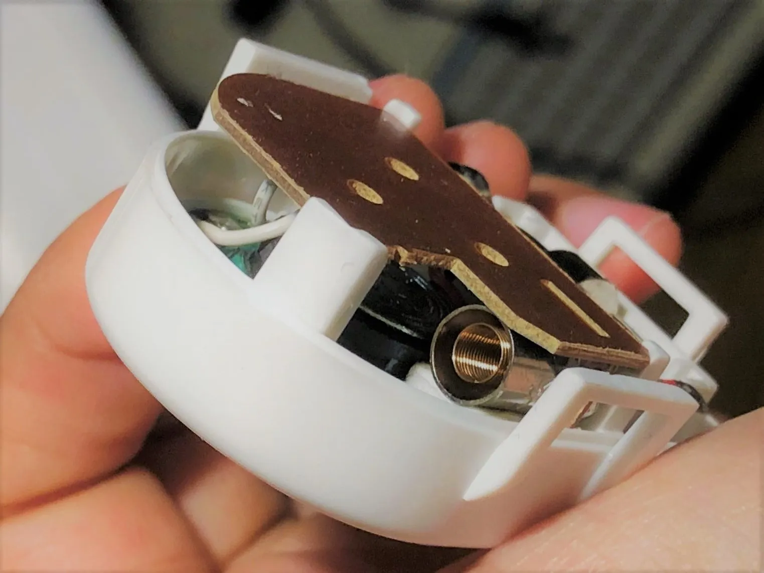
I was able to remove the lid without breaking the case by using a small flathead screwdriver to gently bend and loosen the lid’s brackets. Separating the two halves of the case exposed the tan back of the printed circuit board (PCB) and three button batteries in the lid
The base of the case has three posts that fit into corresponding holes in the board to hold it in place. The lid has three spacers along its inner sides that frame the board to keep it at a distance from the inside of the lid. This ensures sufficient room for the components in between.
Major Components
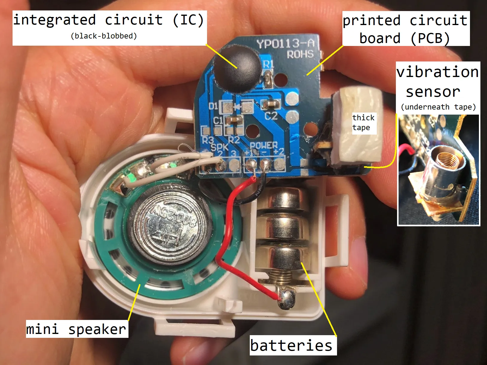 Major components of the vibration activated sound module. Printed circuit board (PCB) and black-blobbed integrated circuit (IC), vibration sensor, mini speaker, and batteries.
The vibration activated sound module is an assembly of several different components:
- 3x Button battery (LR44/AG13)
- Printed circuit board (main board + accessory board)
- Chip on Board (Integrated Circuit?)
- Vibration sensor (made of metal spring and cylinder)
- Mini speaker (8Ω 0.25W)
Components in Detail
Batteries
This module is powered by three LR44 1.5V button cell batteries for a total of 4.5V. I wonder how much total audio clip play time that ultimately translates to. I determined the battery type by looking at the batteries themselves, but the case’s lid also makes the battery needs known (“DC 1.5Vx3” and “AG13(LR44)”) – this is how I learned that LR44 batteries are also known as AG13.
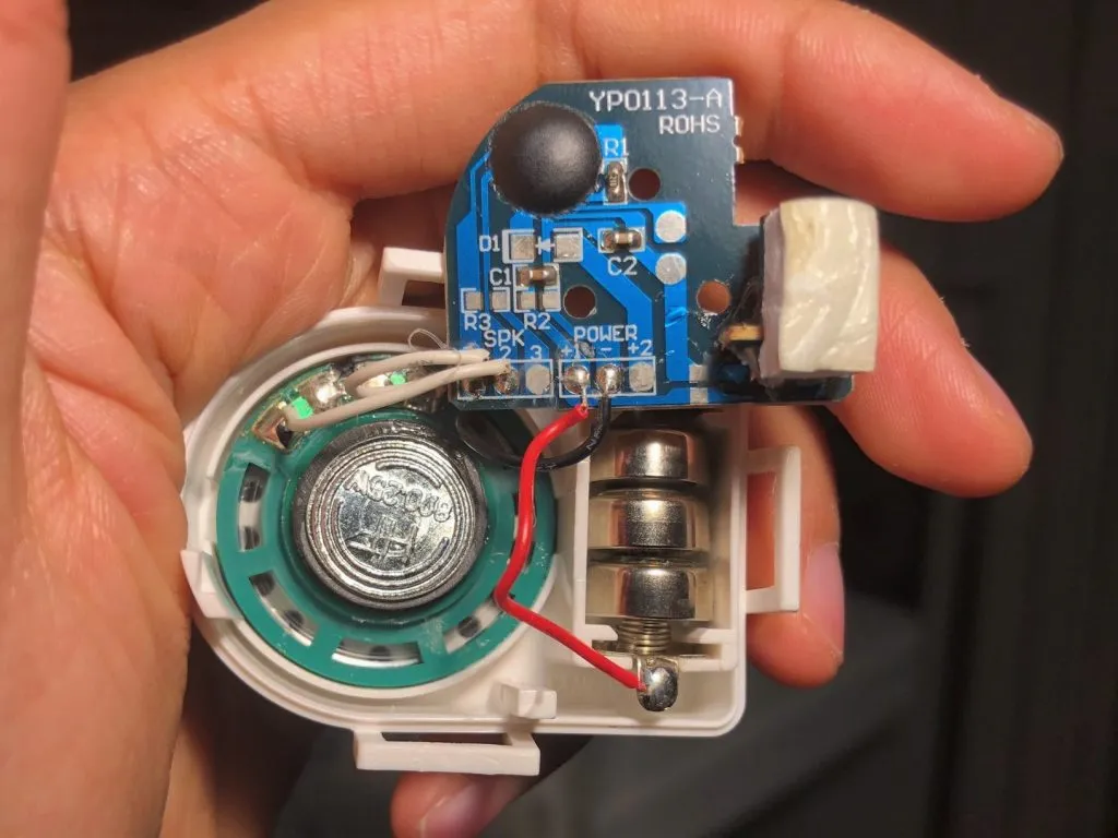
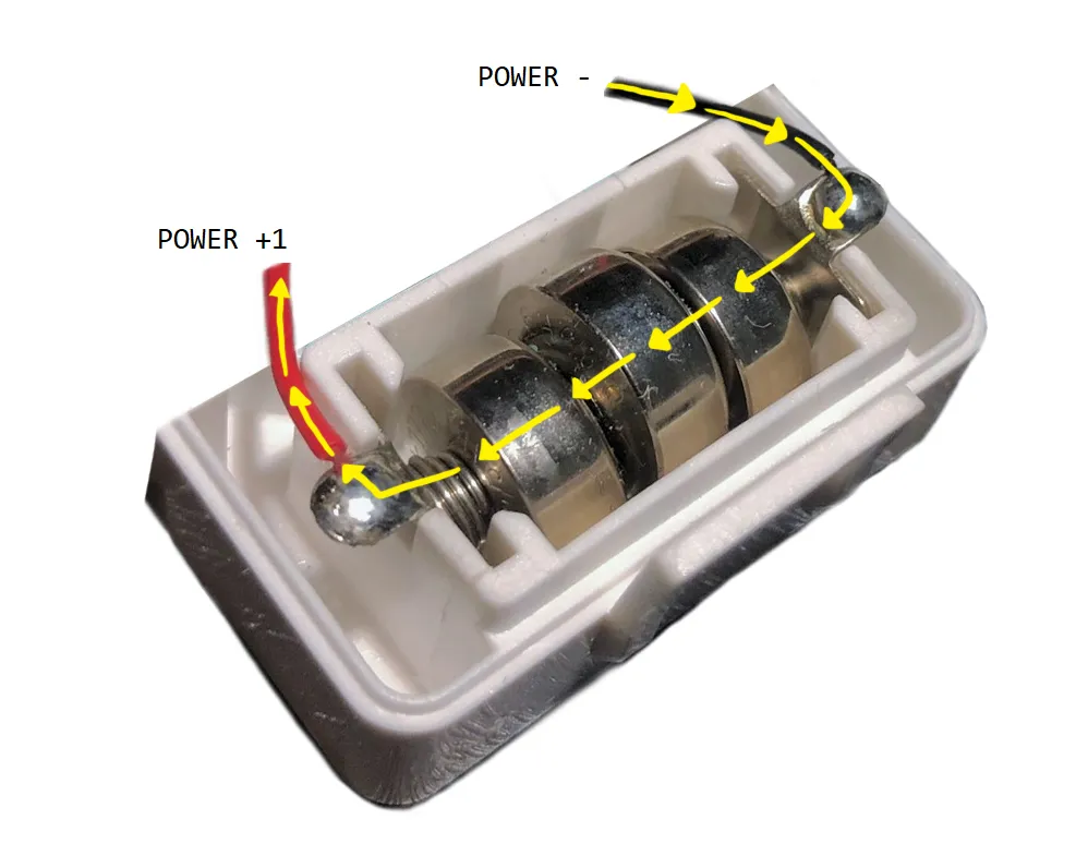 How current flows through the battery component. The black wire is soldered to POWER – and the red wire is soldered to POWER +1 on the circuit board.
The Printed Circuit Board (PCB)
The back of the board is tan/brown. The front is blue and has everything on it — it has all of the traces (light blue lines) and labels, and all connections and soldering are done on this side. In other words, the connected components are surface-mounted rather than through-hole mounted to the board and the type of capacitors and resistors soldered to it are known as SMDs (surface mount devices).
A PCB consists of multiple layers sandwiched together (we won’t go into all of them). The soldermask is a thin, insulating and protective overlay that gives this board its blue colour, but more importantly, it selectively exposes parts of the board’s metal traces as contact points (I don’t know what else to call them) that may be soldered to or tested with. The silkscreen is the layer with the white, human-readable text labels and goes on top of the soldermask.
More info on PCB basics: 1
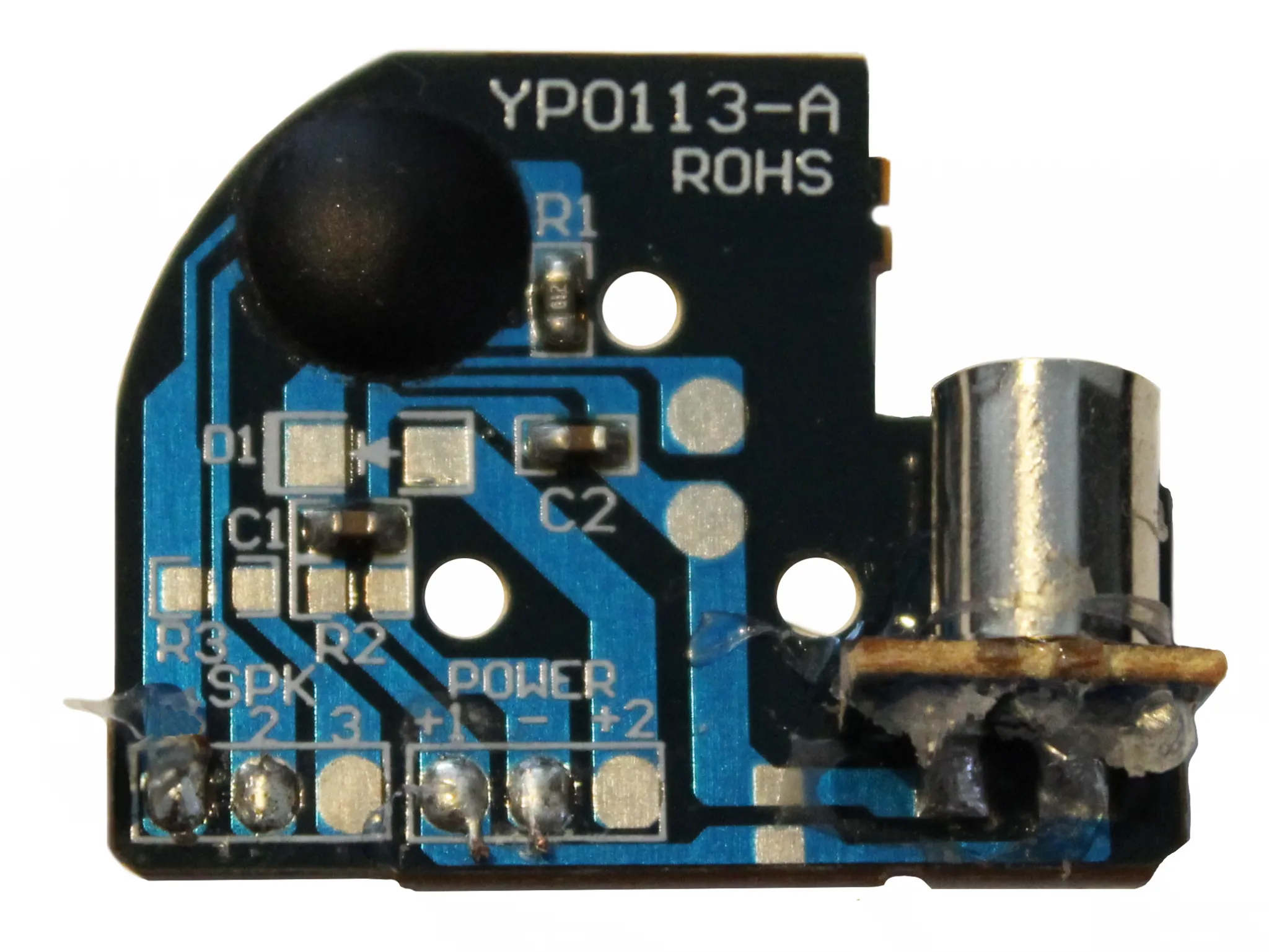 Circuit board (speaker and power wires not shown). After a while of fiddling, some of the wires fell off! The wires to SPK 1 and 2 (both white), POWER +1 (red) and – (black) are not shown but you can see the solder joints that remain. Note: This is a composite image I made to avoid confusion by hiding the wire to SPK 1 which is still dangling off the board.
Let’s look at the labels and stuff on the board. There will be a current flow diagram at the end of this section to tie them together.
“YPO113-A” and “RoHS”
Our board has two large identifying labels at the upper right corner. YPO113-A: likely the board’s item code (I can’t find info on it, maybe it is internal to the company that made it). RoHS: means that this circuit board is compliant with the [Restriction of Hazardous Substances (RoHS) Directive](Restriction of Hazardous Substances (RoHS) Directive) (the board does not exceed the allowed amounts of restricted materials such as lead, mercury, etc. and the [solder must be lead-free](solder must be lead-free)).
Capacitors, Diodes, and Resistors
C = capacitor, D = diode, R = resistor. These indicate what kind of component should be soldered on. Notice the white brackets that show how the component should be oriented. On this module, only some of the available contacts are used (C1, C2, R1) while others (D1, R2, R3) are not*.
“C1, C2”: Capacitors store electrical charge – I think C1 and C2 are used to power audio playing even after contact is broken between the vibration sensor’s parts (i.e. after the circuit becomes open again).
“R1”: Resistors limit current passing through and are usually used to prevent unintentionally destroying components that have limited current tolerance. The line that R1 uses goes in and comes back out of the black blob; I can’t tell from just looking at it which way the current is flowing because there is no label, and resistors themselves do not have polarity. I think it would be possible to find out by scraping away a bit of the soldermask near each end of the resistor to expose test points and use an LED (which does have polarity) to determine the direction of the current.
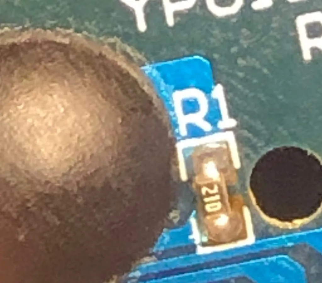 SMD resistor at R1. This resistor has a surface-mount marking on it – it looks like it says “21D” and based on the information and pictures in SparkFun’s guide on resistors it is an E96 resistor with a value of 162kΩ.
Power
“POWER +1, – , +2”: The board’s positive terminal (POWER +1) is connected by a red wire to the positive terminal of the battery component. Ground (POWER -) is connected to the negative terminal of the battery component. The unused POWER +2 appears to be another positive terminal and would work the same way as POWER +1. If you look very closely, the trace associated with POWER +2 goes up and stops at the first contact for D1. I believe the “2” in POWER +2 just means that it is terminal number two rather than that it uses/draws a different amount of power — this confused me!
Speaker
“SPK 1, 2, 3”: The mini speaker is connected by white wires to SPK 1 and 2. SPK 3 is unused. Refer to the Mini Speaker and Speaker Polarity sections of this post for more details. I will note ahead of time here that I’m not totally sure what the unused SPK 3 is for, but I do see that a resistor or connection would need to be added to R3 since SPK 3 goes to a dead end.
The “Black-Blob”
The conspicuous black epoxy resin blob conceals a chip that contains instructions and the Cars II audio clips for the module. The chip is attached to the board with very fine wires and the epoxy resin further secures the chip to the board.
The black blob is a commonly seen feature on circuit boards and is part of the chip-on-board (COB) manufacturing process. From what I’ve gathered, the main reasons why this technique is so popular are because:
- Application is fast and easy,
- It is cheaper than adding the chip at a later production stage,
- It secures the thin wire bonds and protects them from breaking, and
- Once the blob has melded onto the chip and board and dried, it is practically impossible to access the chip encapsulated within and therefore the blob protects any of the product’s logic (intellectual property!) that is stored within. More on the black blob: 1
Unlabeled
Some spots in the traces are exposed and don’t have a label. I think they are supposed to be test points – an easy way to check if the circuit is working with (maybe) a multimeter or other indicator. For example, I was able to light an LED bulb by touching the two square points to the left of the vibration sensor.
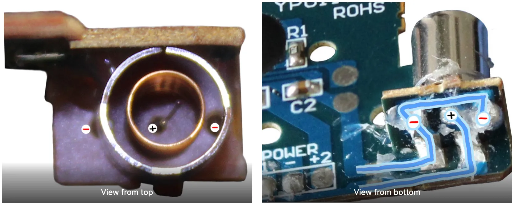
The accessory board (for the vibration sensor)
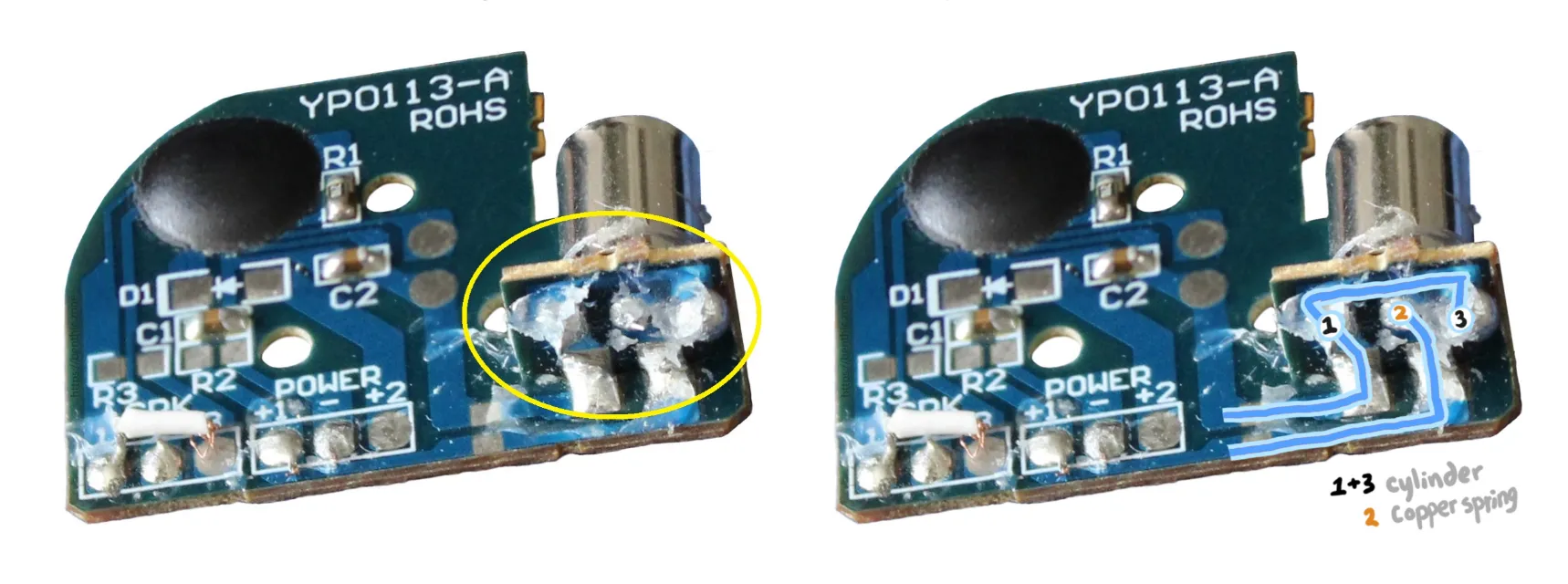
At first I wondered about the asymmetric shape of the circuit board – why isn’t it entirely rounded-off at the top to match the shape of the case? It turns out that the “missing” portion is not really missing but is used as the platform for the vibration sensor; it has traces that help join the vibration sensor with the rest of the circuit on the main board. Since the hot glue makes the traces hard to see, I’ve outlined them below:
The two small tabs on this smaller board appear to match the tabs on the bigger board which suggest that the two pieces were originally connected together. The overall board was likely designed and cut specifically for the smaller board to be snapped off easily at module assembly time to be used as the vibration sensor’s platform. This is an efficient use of materials and probably helps streamline the board’s manufacturing process.
I will discuss the vibration sensor itself in a dedicated section further down in this post.
Current Flow Analysis
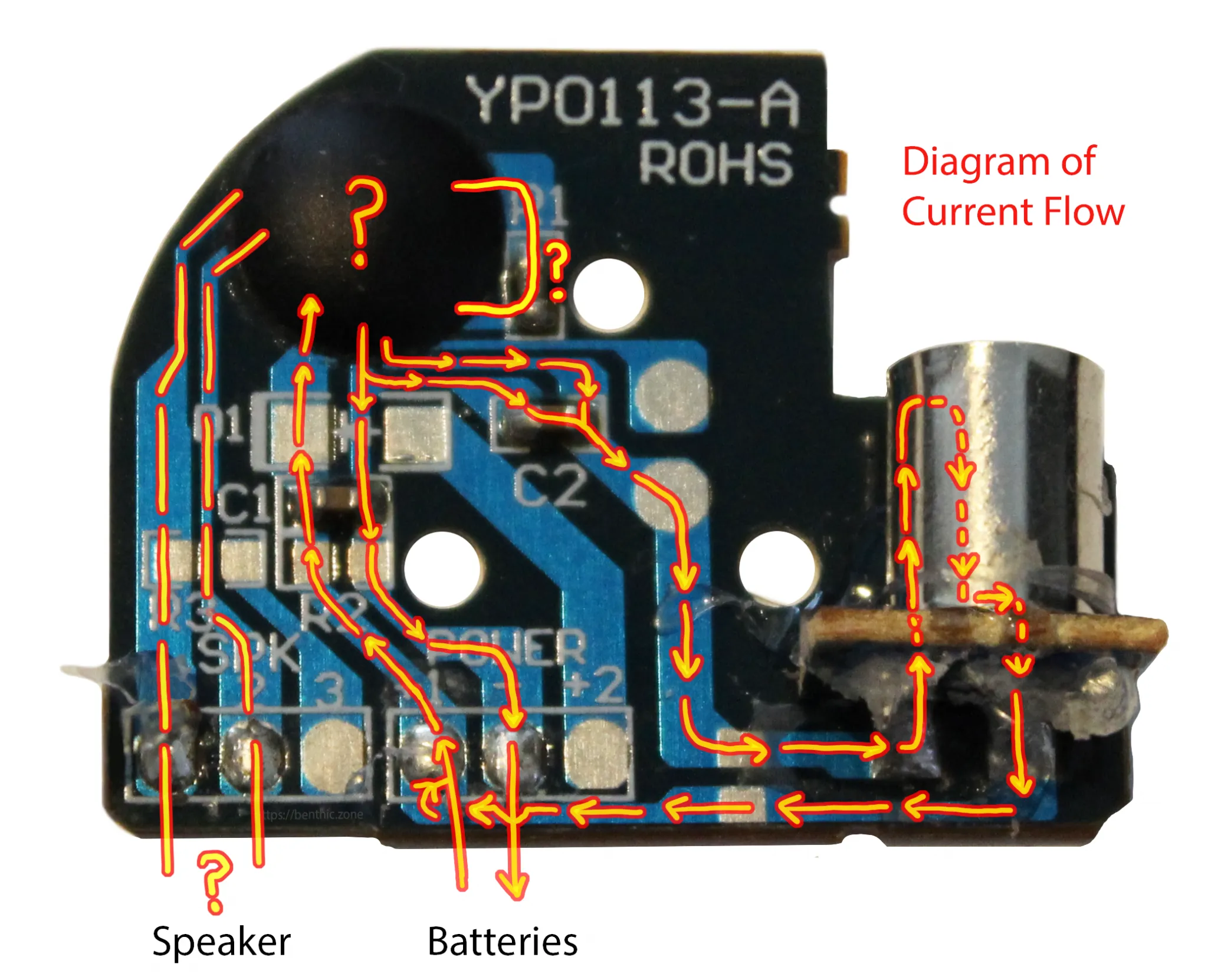
Diagram of current flow. Most of this diagram is complete. I have not yet figured out speaker polarity for a variety of reasons; one being that the module is currently in a broken state 🙁 — so I’ll update this if/when I am able to do some testing.
Possible Current Flow Alternatives
My ponderings about the unused D1, R2, R3, SPK 3, POWER +2:
Maybe this module was designed for reuse with similar toys in mind and therefore the board supports having slightly different configurations from this one. And/or the reason may be as simple as wanting to have an alternative option for soldering the wire orientation while still achieving the same results, such as:
-
Instead of using SPK 1, use SPK3 with R3 where R3 is just a connecting wire with negligible resistance. This assumes SPK 1 and SPK 3 are the same.
-
Instead of using POWER +1 with C1, use POWER +2 with D1, C1, and R2 instead (example diagram and comparison below):
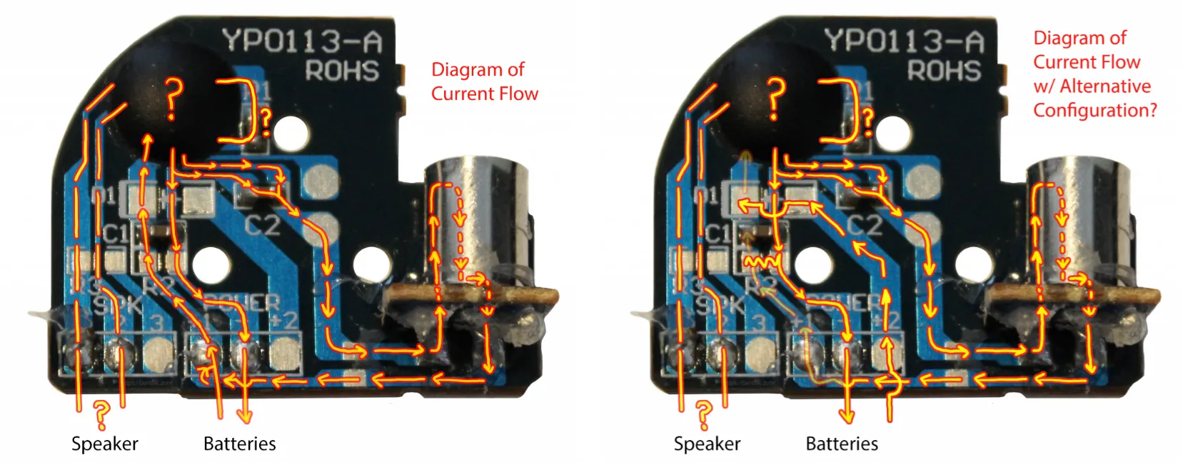
Left: Flow of current using POWER +1 and C1. Right: Flow of current using POWER +2, D1, C1, R2
Mini Speaker
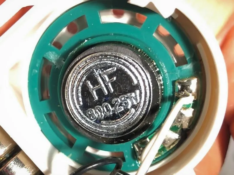 This speaker is rated at 8Ω0.25W
Impedance and Power
The lettering on the back of the speaker says “HF” (High Fidelity?) and “8Ω0.25W“. The latter means that the speaker is rated at 8 ohms of impedance (which is similar to resistance) and uses 0.25 Watts of power.
Speakers normally have a 4Ω, 8Ω, or 16Ω impedance rating, where a higher number rating means less power that the speaker needs to draw from a connected component (e.g. an amplifier). Thus, the connected component should be rated to handle the same or higher amount of impedance for the speakers to play audio effectively and without concern for breakage. I found a comparable 8Ω0.25W mini speaker in the Adafruit store that notes a 0.5W maximum input which indicates a range of tolerance for the amount of power passed through; I’m guessing my speaker is roughly the same.
More info on speaker impedance: 1,2,3,4
Polarity
The speaker has four terminals; only the two on the far ends of this one are used/soldered to the PCB, at SPK 1 and SPK 2 using white wires. I don’t know which one is + and which is -. I was hoping to be able to determine speaker polarity by markings on or near the terminals but I did not see any. Interestingly, one way to tell if the speaker polarity is wired up correctly is to see the speaker cone move outwards and then inwards (rather than the other way around) when audio plays (but that won’t confirm which terminal is what). However, the cone faces the lid and the speaker was very difficult to remove from the plastic housing (superglue…?), so I couldn’t examine it as thoroughly as I wanted to and I’m hesitant to break it open just yet.
More info on speaker anatomy and polarity: 1
I’m roadblocked from further testing because I unintentionally broke most of the wire connections at the solder joints and I can’t fix it right now without soldering and I just haven’t gotten to it. Although I recreated the circuit with some test leads, the circuit is finicky at best. If/when I repair it I will update this post with more information.
Vibration Sensor
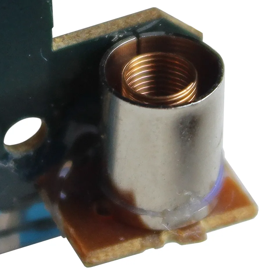
Vibration sensor. A metal cylinder around a coiled copper spring, mounted on a platform that connects to the rest of the module.
To refer to this component as a vibration sensor seems to be the most accurate and appropriate.
Vibration is defined as,
Periodic back-and-forth motion of the particles of an elastic body or medium, commonly resulting when almost any physical system is displaced from its equilibrium condition and allowed to respond to the forces that tend to restore equilibrium.
Source: Brittanica
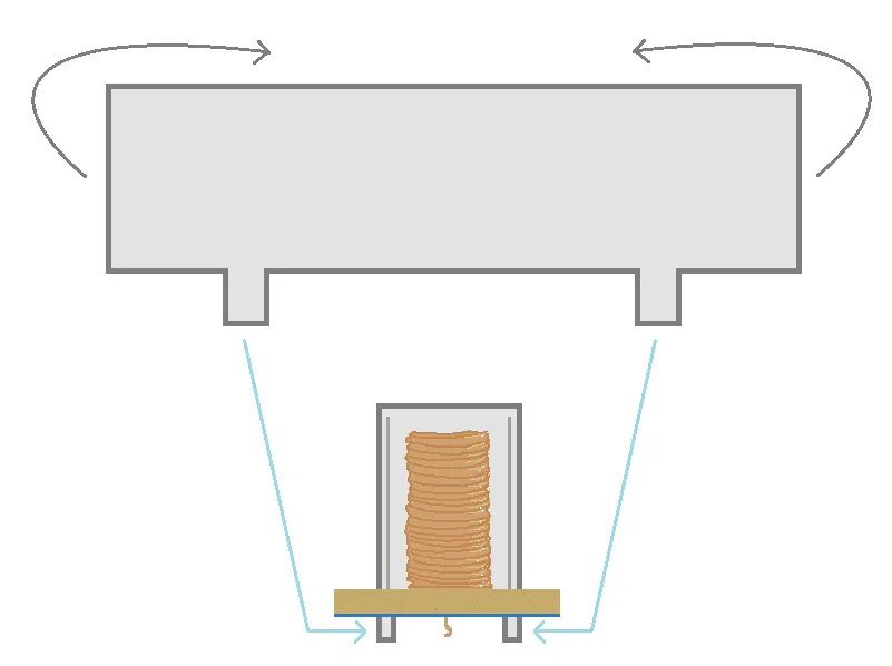
The behaviour that this component relies on fits this description. For audio playback to be triggered, the module only has to be jostled enough to cause the spring to wobble and make temporary contact with the surrounding cylinder.
The vibration sensor essentially serves as a “normally open” switch: The two non-touching parts of the vibration sensor have to make temporary contact with each other to close the module’s circuit which is otherwise open by default.
If you were to move the module steadily so as to not sufficiently displace the spring from its equilibrium, the circuit will not close and audio will not play.
The construction is very simple and cost-effective — the platform/accessory board that the vibration sensor sits on has three holes: two for the cylinder’s “legs” and one for the copper coil’s end to pass through. They are soldered to the traces on the underside of the board. When the spring touches the cylinder and closes the circuit, the current flows from the cylinder (-) to the spring (+).
 The cylinder that surrounds the spring is essentially a rectangular piece of metal rolled over on itself.
Below is a video demo of the vibration activated sound module using a green LED to show that:
- Nudging the spring to make contact with the surrounding cylinder triggers audio to play,
- Electrical current flows from the cylinder to the spring. LEDs are a simple way of testing current flow because they are diodes (a diode is a component for which electrical current flows primarily in one direction from one lead to the other).
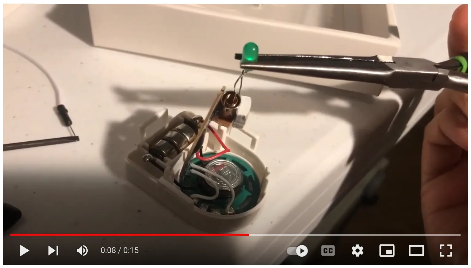
Demo (click above thumbnail to view video). Nudging the spring to make contact with the surrounding cylinder triggers audio to play. The LED shows that electrical current flows from the cylinder to the spring.
One thing I noticed was that merely closing the circuit with the LED was not enough to trigger audio to play. There had to be direct contact between the spring and cylinder. I’m not sure how to explain why this is the case, but my guess is that the LED draws power and the remaining amount that returns to the IC is not enough to fully power the rest of the module.
Vibration sensor design choices
Consider the possible approaches and design choices you could make to create any sort of movement-dependent mechanism that may be used in a circuit to trigger some follow-up behaviour. There are many, and we would not be limited to the category of vibration sensors. However, I think I may save that discussion for a separate post and focus on basic vibration sensors and the current design before us.
Factors that can directly affect the vibration sensor’s sensitivity
We must ask, “how much would the spring have to move and bend in order to make contact with the surrounding cylinder?” and identify variables for the current vibration sensor’s features that could contribute to a different response to this question:
- Overall spring stiffness/flexibility: less likely to bend/wobble and touch the cylinder.
- Spring coil wire gauge: thicker gauge = less flexible, thinner gauge = more flexible.
- Spring coil diameter/height
- Distance between the spring and the inside of the cylinder.
Factors that can indirectly affect the vibration sensor’s sensitivity
There was also a piece of thick double-sided tape wedged between the vibration sensor and the speaker as an additional measure to hold the board in place. With the previously mentioned black pouch anchoring the vibration activated sound module to the body of the toy, as well as the various posts and tape keeping things fairly set in place inside, the vibration sensor is less likely to be unintentionally triggered.
Other variations of vibration sensors available on the market
Here are some vibration sensor types that are similar to the one featured in this post:
Spring-and-cylinder (non-directional*): This is the type of vibration sensor featured in this post. Here is one I found online with a comparable design: Common 12V 10M Ohm Vibration Sensor Switch (specs vary)
Spring-and-pin (non-directional*): This design appears to be the most commonly available. It is similar to our vibration sensor, except instead of a cylinder around the spring, a long pin is placed in the middle of the spring. The idea is still there — the spring would need to move enough to make contact with the pin to close the circuit. Adafruit has several different spring-and-pin vibration sensors that vary in sensitivity based on some of the factors we discussed earlier: Fast Vibration Sensor Switch (Easy to trigger) Medium Vibration Sensor Switch Slow Vibration Sensor Switch (Hard to trigger)
Spring-and-pin (directional*): Flat Vibration Switch – Breadboard friendly
* Non-directional vs Directional. Non-directional vibration sensors don’t discriminate against how or from where they are bumped or jostled (at least compared to directional vibration sensors). Directional vibration sensors are made to be more easily triggered if bumped from a certain side.
There are many other types and variations of “vibration” sensors out there that are beyond the scope of this discussion — some of which are far more advanced to meet sensitivity and accuracy requirements, can sense flexing, and even allow you to measure the magnitude of vibration. What you need to use for your own projects will depend on your needs.
Closing Thoughts
I found myself spending a lot more time observing and thinking about the module’s features while writing this post and putting images together than when I was just tinkering about.
This reminded me of the student in Samuel H. Scudder’s essay, Look at Your Fish! which my college Vertebrate Biology teacher introduced to my class through a similar exercise.

Every time I thought I had run out of things to look at, I kept finding more.